
The injector CW campaign was interrupted during a few weeks to fix two technical issues which appeared in a row just after resuming this activity at the beginning of 2023. For the first one, a fuse and few transistors were found damaged in the power supply of the second source coil. Procurement of new components was relatively fast and allowed fixing the power supply in a timely manner. The second difficulty came immediately after resuming injector operations and was linked to the power supply of the magnetron. On-site investigations did not allow to determine the reason of this failure. The power supply was replaced by a spare one from same manufacturer with different remote control interfaces. Yet few adjustments were needed to accommodate a different communication protocol and physical interfaces. The control system group worked closely with the injector group to update the local control system. Tests were performed in manual and remote modes to confirm signal synchronization with timing system, interlocks and operability from injector OPI (Operator Interface). Eventually, the injector operations with deuteron beam resumed on 29 March with the 11mm PE (plasma electrode). While plasma conditioning is organized during nights, beam extractions is performed during evening shifts and reached 150 mA extracted current at 100% DC (duty cycle) in the last days. Emittance measurements are performed at 5% DC for different beam extraction conditions. The objective is to gather enough data to compare results with the ones of previous injector campaign in 2022 using same PE diameter.
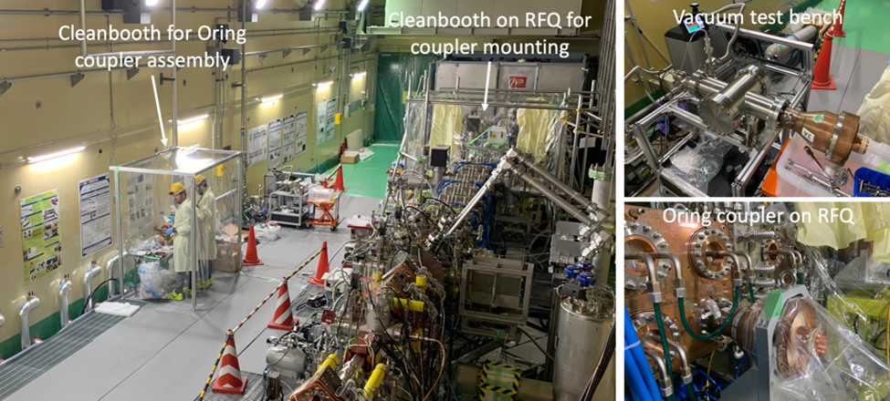
The main reason preventing injector operations during the daytime is related to RFQ activities. Indeed, the assembly of the Oring couplers was performed in a cleanbooth mounted in the vault. After each assembly, the coupler was mounted on a local vacuum chamber next to the cleanbooth to perform vacuum leak test. Though the coupler assembly procedure was well detailed, the percentage of successful leak tests was rather low for the first assemblies. A number of adjustments were introduced in the assembly sequence in order to obtain vacuum tight assemblies. Once validated on the vacuum test bench, each Oring coupler was mounted on the RFQ. Special care was given to the cleanliness aspects with the use of a large cleanbooth installed on both sides of the RFQ and able to host 2 operators. A smaller cleanbooth was installed in the first one around the RFQ port on which was mounted the Oring coupler. After completing the installation of the 8 Oring couplers, vacuum was pulled in the RFQ for a global leak test. After tightening further few bolts, the RFQ vacuum leak test was validated. The RFQ was brought back to atmospheric pressure to allow the assembly of the coaxial lines, which should start just after removing all the scaffoldings used for coupler assembly and also after reconnection of water piping and cables on the couplers.
Meanwhile, the conditioning of the first pair of brazed couplers on RFQ RF chain 4A was terminated in March. It reached 96.3% duty cycle at 196 kW but with 130 kW of reflected power. While the first brazed coupler can be considered as fully conditioned, the second coupler was not exposed to full RF power and its conditioning should be completed later. The HPTB (High-Power Test Bench) was dismounted last month to allow activities on the MEBT SSPA and remounting of the coaxial lines in view of the LIPAc beam operations.
Another RF test bench was mounted on the RFQ RF chain 3B to condition the spare ceramic disks of the Oring couplers. A first ceramic disk was mounted and conditioned up to 150kW at 55% DC, but the test was put on hold as temperatures were reaching 86°C on the RF window flanges. A second ceramic disk was mounted for comparison and is under testing.
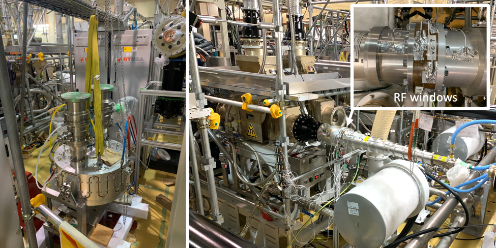
Conditioning of spare ceramic for Oring couplers on RFQ RF chain 3B (right)
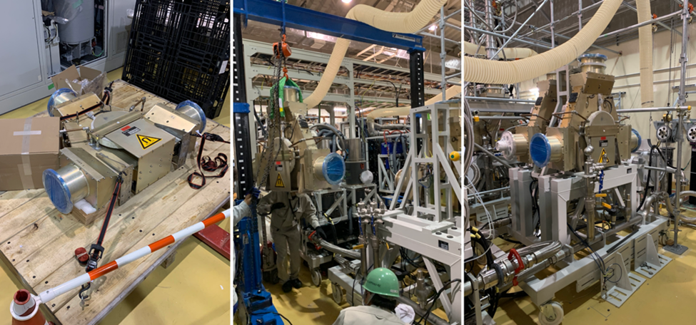
After their delivery and unpacking in Rokkasho BA site, the circulators 1A and 1B have been mounted on the RFQ RF module #1. Besides the heavy components and the limited space between RF modules and control cubicles, the detailed procedure prepared in advance allowed a smooth assembly operation. A water pressure test was performed after reconnection of water piping and get successful after fixing a few leaks. Measurements of RF characteristics for each circulator were performed successfully at different temperatures. The position of the circulators was adjusted during an alignment campaign with laser tracker. Before connecting the circulators to the RFQ with coaxial lines, a last RF power test will be performed by mounting a RF load at the output of each circulator.